



An insulation resistance tester is used for IR testing to measure the resistance of a material that’s meant to block current flow, like the insulation around a wire or the barrier between a product’s internal components and its outer chassis. Good insulation should show high resistance. A low reading means current is finding a path it shouldn’t, usually because the insulation has degraded, absorbed moisture, or picked up conductive contamination.
The test works by applying a DC voltage between two points, such as a conductor and ground, and measuring the resulting leakage current. Resistance is then calculated from that voltage and current using Ohm’s law. Most insulation resistance testers do this calculation automatically and display the result directly in ohms, megohms, or gigohms.
Insulation Resistance Test vs. Hipot Test: What’s the Difference?
Both tests check the same thing, insulation integrity, but they do it differently and catch different problems.
A hipot test applies a much higher voltage for a short duration and checks whether the insulation breaks down completely under that stress. It’s a pass/fail test built to catch gross insulation failures, like a nicked wire or a missing barrier, before a product ships.
An insulation resistance test applies a lower, steady DC voltage and measures resistance as a number, not just a pass/fail result. This makes it better at catching gradual degradation, like insulation that’s absorbed moisture or is starting to break down, before it becomes a hipot failure.
Because they catch different failure modes, many production lines run both tests as part of the same sequence rather than choosing one over the other.
Test Voltage and Minimum Resistance Values
The test voltage and minimum acceptable resistance for an insulation resistance tester both depend on what you’re testing and which standard applies. As a general reference point, field-maintenance standards like IEEE 43 use test voltages roughly matched to the equipment’s rated voltage, for example 500 VDC for systems under 1 kV, and set minimum acceptable resistance using a rule like (rated kV + 1) megohms, corrected to a standard reference temperature of 40°C. Product safety standards used in manufacturing, like IEC 60335-1 or IEC 62368-1, set their own required minimums, which are typically different from the field-maintenance figures above.
Step-by-Step On How To Use An Insulation Resistance Tester
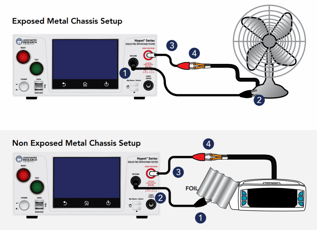
- Disconnect the device from power and make sure it’s fully de-energized before connecting test leads.
- Connect the test leads. One lead goes to the conductor or winding being tested, the other to ground or chassis, depending on what you’re measuring.
- Select the test voltage appropriate for the product or standard you’re testing to.
- Apply the voltage and hold it for the time specified by the standard you’re following, often one minute for a simple spot reading.
- Record the resistance reading. Compare it against the applicable minimum value.
- Discharge the DUT after the test completes. Insulation with any capacitance will hold a charge after voltage is removed, so proper discharge matters for operator safety.
Reading the Result: Beyond a Single Number
A single reading from an insulation resistance tester tells you whether insulation passes or fails at that moment, but it doesn’t tell you much about trend or moisture content on its own. Two additional measurements can add more insight:
- Polarization Index (PI): the ratio of the resistance reading at 10 minutes to the reading at 1 minute. A rising ratio generally indicates dry, healthy insulation. A flat or falling ratio can indicate contamination or moisture.
- Dielectric Absorption Ratio (DAR): a similar concept measured over a shorter window, typically the 60-second reading divided by the 30-second reading.
These extended tests are more common in field maintenance and large equipment testing than in production-line compliance testing, where a single spot reading against a standard’s minimum is usually sufficient.
Choosing an Insulation Resistance Tester
The right tester depends on how you’re using it. For a single spot-check as part of a broader safety test sequence, look for an insulation resistance tester that combines insulation resistance with hipot and ground bond testing in one instrument, so you’re not switching between separate devices. For field maintenance work involving PI or DAR readings, you’ll want a tester built to hold voltage steady over longer test windows and log readings over time.
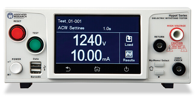
Our Hypot® Series include insulation resistance testing alongside AC/DC hipot and ground bond, in the same instrument, with a range of 30 to 1000 VDC and 1 MΩ to 50 GΩ.
Hypot® Series Hipot Tester
FAQ
- What is an insulation resistance tester? An insulation resistance tester is an instrument that applies a DC voltage to a product’s insulation and measures the resulting leakage current, expressing the result as a resistance value in megohms or gigohms. It’s used to check whether insulation is in good condition or has degraded from moisture, contamination, or damage.
- What’s the difference between an insulation resistance test and a hipot test? A hipot test applies a higher voltage briefly to check for a hard insulation failure. An insulation resistance test applies a lower, steady voltage and measures resistance as a number, which makes it better suited to catching gradual insulation degradation before it becomes a hipot failure.
- What’s a good insulation resistance reading? A commonly used minimum is 1 megohm per 1,000 volts of operating voltage, though the actual pass threshold depends on the applicable product safety or maintenance standard.
- How long should I apply voltage during an insulation resistance test? A basic spot reading is typically taken after holding voltage for about one minute. Extended tests like Polarization Index readings hold voltage for up to ten minutes to track how the reading changes over time.

