



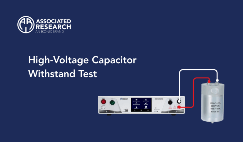
As core passive components in power converters, inverters, electric/hybrid vehicles (EV/HEV), industrial drive equipment, medical devices, and high-voltage power systems, high-voltage capacitors perform critical functions such as energy storage, filtering, and electromagnetic interference (EMI) suppression. Due to the inherent charge-storage characteristics of capacitors, the reliability of their insulation systems not only directly determines the operating lifetime and stability of the product but also plays a critical role in the overall electrical safety of the system.
The Dielectric Strength Test, commonly known as the withstand voltage test or HiPot Test, is an essential safety compliance test. Its purpose is to verify that the capacitor’s dielectric material, insulation structure, package terminals, and internal electrodes can withstand the specified high-voltage and time stresses without dielectric breakdown or abnormal leakage current.
A withstand voltage test is not simply a matter of “applying high voltage.” AC and DC test voltages induce fundamentally different electrical stresses and dynamic responses in the capacitor dielectric. Therefore, before selecting the test method, it is essential to understand the behavior of capacitors under AC and DC voltage.
Physical Mechanism of Dielectric Breakdown in Capacitors and Purpose of the Withstand Voltage Test
For an ideal capacitor, the charge (Q), capacitance (C), and applied voltage (V) follow the fundamental physical relationship:
Q = CV
When a voltage is applied across a high-voltage capacitor, an electric field E is generated within the dielectric material:
E = V/d
where d is the thickness of the dielectric layer.
When the applied electric field strength exceeds the critical breakdown field strength of the dielectric material (Breakdown Field Strength, E_bk), avalanche breakdown or thermal breakdown may occur within the dielectric. This phenomenon can lead to the following systematic failures:
- Sharp decrease in insulation resistance
- Rapid increase in leakage current
- Partial discharge
- Permanent damage to the dielectric material
- Short circuit
- Capacitor failure
- In severe cases, arcing or catastrophic component failure
Therefore, the primary purpose of the withstand voltage test is not to verify whether the capacitor “can be charged normally,” but to determine whether its insulation system has sufficient electrical withstand capability under the specified voltage and duration.
Electrical Characteristics of AC and DC Withstand Voltage Tests
The most important point in understanding AC and DC withstand voltage tests is that a capacitor does not behave as the same type of load under AC and DC.
The impedance of a capacitor is:
As the frequency f increases, the capacitive reactance decreases.
This means that when an AC voltage is applied to a capacitor, it produces periodic charging and discharging currents. When a DC voltage is applied, the capacitor initially charges, and under ideal conditions, the current subsequently approaches zero. This is one of the key differences between AC and DC withstand voltage tests.
AC Withstand Voltage Test (AC Hipot Test)
When an AC test voltage is applied,
V(t) = Vpeak sin(ωt)
the capacitor will continuously generate a capacitive charging and discharging current i(t):
Therefore, even if the capacitor has not experienced dielectric breakdown, a significant capacitive current will still be present whenever an AC voltage is applied.
DC Withstand Voltage Test (DC Hipot Test)
After a DC voltage is applied, the capacitor initially undergoes charging:
When the voltage reaches a steady state and dVdt = 0, the charging current of an ideal capacitor becomes zero.
In actual components, dielectric losses, leakage current, and current from the test system itself will still be present. Therefore, a practical DC Hipot test does not have zero current; instead, leakage current and the insulation condition are the primary parameters monitored.
Evaluation of the Benefits of DC Withstand Voltage Testing for High-Capacitance Capacitors
Consider a high-voltage capacitor with a capacitance of C = 10 μF. If an AC withstand voltage test is performed according to the specification, with an applied voltage of V = 1 kVRMS at 50 Hz, the ideal capacitive current is approximately:
IAC = 2πfCV = 2π × 50 × (10 × 10−6) × 1000 ≈ 3.14 A
In other words, even if the component has no defects, the test equipment must continuously supply an AC current as high as 3.14 A.
If the capacitance is larger or the AC test frequency is increased, the test current will increase further.
This creates several challenges:
- The test equipment must provide a higher output current.
- The capacitor undergoes repeated charging and discharging.
- Additional power losses and heat generation may occur in the capacitor.
- The test equipment must distinguish normal capacitive current from actual insulation leakage current.
- AC Hi-Pot testing of high-capacitance, high-voltage capacitors requires higher equipment capacity and testing costs.
Therefore, for high-voltage capacitors with large capacitance values, a DC withstand voltage test can eliminate continuous AC charging and discharging currents, allowing the test energy to focus entirely on evaluating dielectric insulation quality and leakage current characteristics.
Equivalent Conversion and Comparison of AC and DC Test Voltages
According to international safety standards (such as IEC and UL), the peak insulation stress of an AC voltage is times its RMS value. When using a DC test to replace an AC test, an equivalent peak voltage must be applied:
VDC = √2 × VAC,RMS ≈ 1.414 × VAC,RMS
Therefore, for an AC test voltage of 1 kVRMS, the equivalent DC test voltage should be set to 1.414 kVDC.
Comprehensive Comparison of AC and DC Withstand Voltage Test Characteristics
| Item | AC Withstand Voltage Test | DC Withstand Voltage Test |
| Voltage waveform | Periodically changes polarity | Fixed polarity |
| Capacitor charging/discharging | Continuous | Charging occurs during startup |
| Capacitive current | High | Relatively low after reaching steady state |
| Test equipment current requirement | Higher | Generally lower |
| Leakage current evaluation | Must be distinguished from capacitive current | Relatively straightforward |
| Residual charge after testing | Low | High |
| Testing of high-capacitance capacitors | Higher equipment requirements | Generally more convenient |
IEC 61071 Withstand Voltage Test Requirements
In the field of power electronic systems, IEC 61071 (Capacitors for Power Electronics) is one of the key international standards for component-level safety and performance testing. The standard specifies the withstand voltage test requirements between the terminals of high-voltage capacitors:
Table 1
| AC capacitors | DC capacitors | ||
| All | Non-self-healing | Self-healing | |
| AC test voltage* | 1.5 UN | – | – |
| DC test voltage | 2.15 UN | 2 UNDC | 1.5 UNDC |
*The frequency of the AC test voltage shall be 50 Hz or 60 Hz.
The conditions for the type test and routine test are as follows:
| Routine Tests | Type Tests | |
| Test Voltage | Refer Table 1 | Refer Table 1 |
| Test Time | 10s* | 60s |
| Pass Condition | No Breakdown / Flashover | |
*Test time may be reduced to 2s with a 10% voltage increase.
Practical Procedure for High-Voltage Capacitor Withstand Voltage Testing
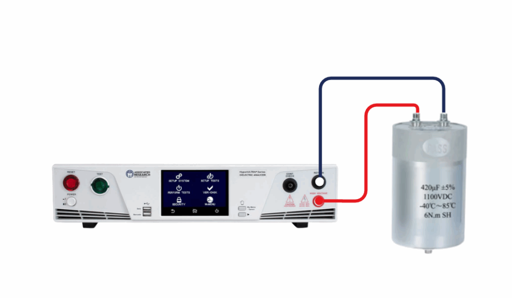
For DC withstand voltage testing of capacitive loads, the following four-stage standard control procedure must be strictly followed to prevent transient inrush current from causing false overcurrent detection and to ensure the safety of personnel and equipment.
- Preset Test Conditions and Parameters: Convert the voltage level according to the applicable safety standard.
If the specified AC test voltage is 1500 VAC, set the DC test voltage to 1500 × 1.414 ≈ 2121 VDC. - Slow Voltage Ramp-Up (Ramp-up Time): Prevent excessive charging current from triggering false detection.
Set a gradual ramp-up time, such as 3 to 5 seconds. When DC voltage is applied, I = C dV/dt. If the voltage rises too quickly, the high charging current may trigger the tester’s overcurrent protection. Gradually increasing the voltage keeps the charging current within a safe range. - Steady-State Dwell and Measurement (Dwell Time): Measure the actual insulation leakage current.
When the voltage reaches the target value (e.g., 2121 V_DC) and is maintained for the specified duration (typically 1 second for production-line testing and 60 seconds for type testing), the capacitor becomes fully charged. At this point, the current measured by the tester represents the leakage current through the dielectric insulation. - Active Discharge and Voltage Ramp-Down (Discharge / Ramp-down): A critical safety requirement for high-voltage capacitors.
After the test is completed, the tester must safely discharge the capacitor through its internal discharge circuit. The voltage is typically required to be reduced to below 45 V, or the discharge must be maintained for at least 3–5 seconds to prevent electric shock hazards to operators.
Associated Research Solution
The HypotULTRA 7800 with Option 15 provides an output capability of up to 6 kVDC/50mA, increasing the current capacity for DCW testing and making it suitable for withstand voltage testing of higher-capacitance components. It also features discharge monitoring to enhance safety and reliability throughout the testing process.
The essence of high-voltage capacitor withstand voltage testing is to verify the integrity and safety of the insulation system through high-voltage electrical stress. Although AC testing can realistically simulate the electric field distribution of components operating under AC conditions, for high-capacitance components, the large charging and discharging currents generated during AC testing not only significantly increase test equipment costs but also interfere with the accurate measurement of insulation leakage current.
By adopting DC withstand voltage testing, engineers can eliminate the interference caused by reactive AC current and accurately evaluate the dielectric’s leakage current and arc response. As long as the two key safety principles—controlled slow voltage ramp-up and active discharge after testing—are strictly followed, DC withstand voltage testing provides an efficient and reliable solution for the design verification and quality control of high-capacitance, high-voltage capacitors.

