



Chassis grounding, also called equipment grounding, connects a product’s metal chassis or enclosure to a common ground reference. If an internal fault causes a live conductor to contact the chassis, that ground connection gives the fault current a low-resistance path to follow, away from anyone touching the outside of the product.
Without a proper chassis ground, a single internal fault could leave the entire chassis energized. Anyone touching it becomes the path to ground instead, which is a serious shock hazard.
Chassis grounding is different from a couple of related terms that sometimes get confused with it:
- Earth ground (PE): a physical connection to the earth itself, usually through a building’s electrical system. A chassis ground is often connected to earth ground, but the two aren’t automatically the same thing.
- Signal ground: a reference point for a circuit’s signals, focused on stable, low-noise operation rather than safety. Signal ground and chassis ground can be connected, but mixing them carelessly can introduce noise or create unwanted current paths.
Why Chassis Grounding Matters
Chassis grounding does two jobs at once.
- It gives fault current a path to travel that isn’t through a person. If a live wire comes loose and touches the chassis, a solid ground connection routes that current away safely instead of energizing the whole enclosure.
- Noise reduction. A well-grounded chassis also shields internal circuits from electromagnetic interference, which matters for accurate measurements and stable operation, particularly in environments with a lot of other electrical equipment running nearby.
How Chassis Grounding Is Verified: The Ground Bond Test
A chassis being grounded in principle isn’t the same as it being verified. That’s what a ground bond test, also called a ground continuity test, is for. It applies a known current between the chassis and the ground conductor and measures the resistance of that connection. If resistance is low enough, current has a clear, low-impedance path to follow in the event of a fault.
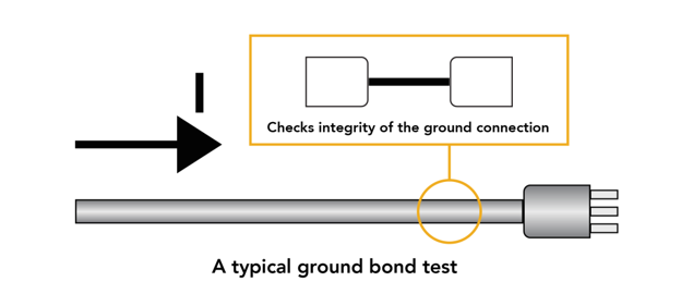
As a general reference, ground bond tests are commonly run at currents ranging from around 100 mA up to 40A depending on the product and the applicable standard, with most standards requiring a maximum acceptable resistance of 0.1 ohms. Higher fault currents in the product’s design typically call for a higher test current to properly stress the ground path.
Basic Ground Bond Test Procedure
- Connect the test leads. One lead to the chassis or exposed conductive part being tested, the other to the ground reference point.
- Select the test current appropriate for the product’s rated fault current and the standard being followed.
- Apply the current and hold it for the duration specified by the standard.
- Record the resistance reading and compare it to the maximum allowed value.
- Repeat at each grounding point if the product has more than one exposed conductive part that needs to be tested.
Choosing Ground Bond Test Equipment
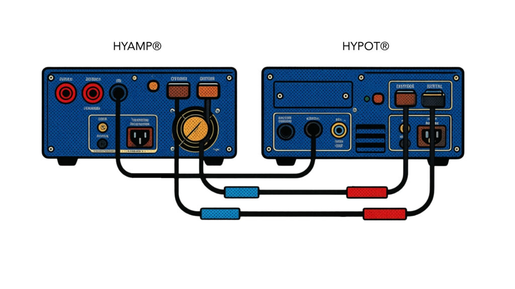
Look for a tester with a current range wide enough to cover the products you’re testing, since a tester built for small appliances may not have the current output needed for larger industrial equipment. If you’re already running hipot and insulation resistance tests as part of the same sequence, an instrument that combines all three, like pairing the HYAMP® Ground Bond Tester with the Hypot® Series, lets you verify chassis grounding without adding a separate test station.
FAQ
- What is chassis grounding? Chassis grounding connects a product’s metal frame or enclosure to a ground reference point, so that fault current has a safe path to follow instead of energizing the chassis itself.
- What’s the difference between chassis ground and earth ground? Chassis ground is the connection between a product’s enclosure and a ground reference. Earth ground is a physical connection to the earth itself, usually through building wiring. A chassis ground is often tied to earth ground, but they aren’t automatically the same connection.
- How is chassis grounding tested? Chassis grounding is verified with a ground bond test, also called a ground continuity test. It applies a known current between the chassis and ground and measures the resistance of that path, confirming it’s low enough to safely carry fault current.
- What’s a good ground bond resistance value? Acceptable resistance depends on the product and the standard being applied, but readings in the range of 0.1 to 1.5 ohms are common thresholds for a passing ground bond test.
- Which standard covers ground bond testing? Ground bond (protective bonding) testing is most commonly specified under IEC 61010-1, the international safety standard for electrical equipment used in measurement, control, and laboratory settings. Other product categories reference their own applicable standard for the exact test current and resistance limits.

