

Electronic products need to pass a series of strict tests to ensure their quality on safety before they go on the market. Among the tests, the Hipot test (also known as dielectric withstand test) is commonly performed and required by all the electrical safety standards. This test is to verify the product’s insulation capability by applying a high voltage. Failing to pass the test may cause electric shocks or possible death while operating the device. Figure 1 shows the most common method to conduct the Hipot test. However, the products designed are varied according to local electric conditions. Such as in figure 1 example, this is specific for the class I product (3 Prongs). How about the class II products (2 Prongs) and other accessories that are not connected to the outlet directly but are a subset that leverages the electricity? This article will demonstrate a few different kinds of Hipot testing setup insights that we accumulated over the years of onsite experience.

Figure 1. Hipot Test Configuration of Class I Products
Different Configuration for Class I and II Products
There are many different types of plug around the world. In most cases, the plug has 2 or 3 prongs. In Figure 2, a 3 prongs plug has two vertical prongs and a round stick. The right prong (known as neutral) may slightly larger than the left prong (known as line). The round stick below those two vertical prongs known as ground. The Class I products have a 3 prongs plug. To conduct the Hipot test, the HV lead of the tester connects to shorted neutral and line prongs and return lead of the tester connects to the ground prong.

Figure 2. Class I and II Products Plug
The main difference between Class I and II products is Class II products do not have the ground prong. The Class I products are commonly designed with metal chassis. The ground prong will prevent the operator from getting electrical hazards when malfunction. Because it connects the metal chassis to the ground, the leakage current will flow to the earth. Figure 3 shows the Class II products (2 prongs) Hipot test setup. The return leads of the tester connects to a piece of aluminum foil that is wrapped around the chassis of the device under test (DUT). Usually, the Class II products are designed with non-metal chassis. The aluminum foil is necessary to create a conductive material around the DUT’s insulation.

Figure 3. Hipot Test Configuration of Class II Products
Active Accessory Hipot Test Requirement and Setup
The active accessories do not have any prongs connect to the outlet, but it doesn’t mean they are not required for the safety test. For some products, the active accessories use a larger voltage and may cause more serious electrical hazards when it is a malfunction. Therefore, some standards have specific descriptions for conducting the accessories’ Hipot test. A great example is IEC 60601-2-2 High Frequency (HF) Surgical Accessory. In the following, we will take this standard as an example and explain in detail the Hipot test configuration:

Figure 4. HF surgical accessory
First, the insulated parts of all active accessories, except handle and connectors, need to be preconditioned by immersion in saline for 12 hours. But the operative conductors and the insulation of active accessories cords need to be protected from contact with saline. When conducting the Hipot test, the entire insulation of active accessories cord shall be immersed in the bath saline. The HV lead of the tester connects to a conductive electrode immersed in the saline bath and the return lead of the tester connects to all of the conductors in the cord (shown in Figure 5)
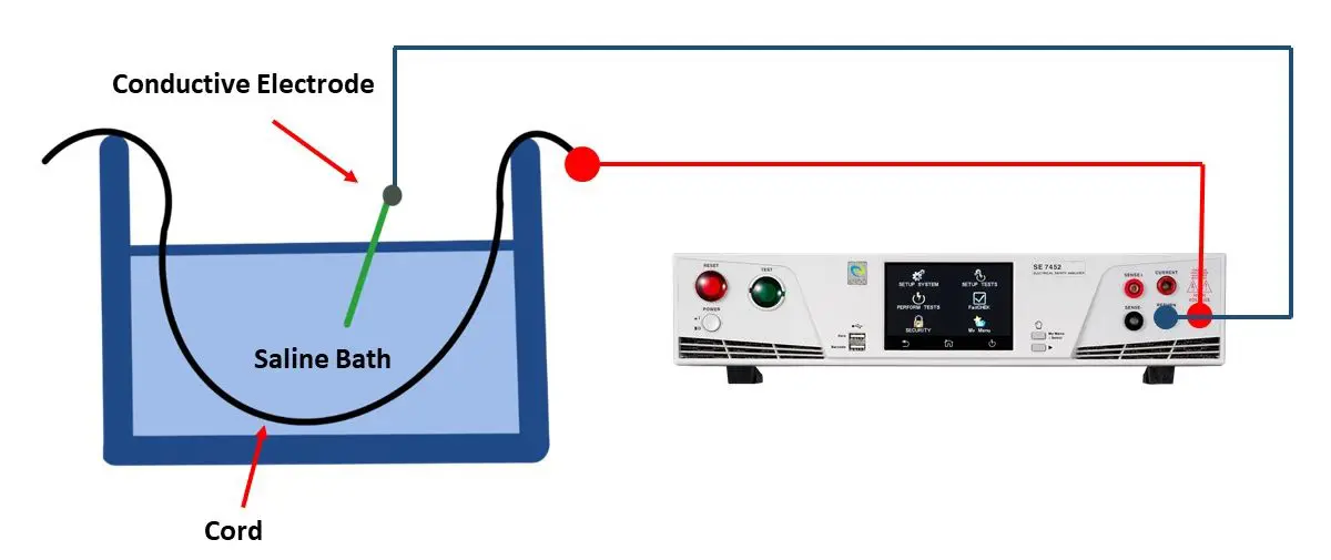
Figure 5. Hipot Test Configuration of Accessory (Except Handle and Connectors)
The handles, electrodes, and connectors are usually wrapped in a porous cloth soaked in saline. This cloth shall cover the entire exterior surface of the handle and extend to the surface of the cord and the active electrode insulation. The midsection of the saline-soaked cloth is wrapped with metal foil. The return lead of the tester connects to the foil and the HV lead should connect to the active electrode simultaneously.
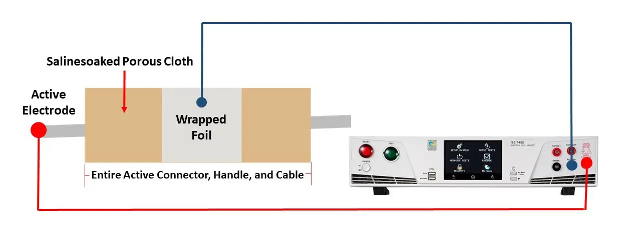
Figure 6. Hipot Test Configuration of Handle and Connectors
To conduct the Hipot test for the active accessories, the testing voltage is rated accessory voltage + 1000V. It can up to 10kV or even higher. If the insulation breakdown or flashover occurs, the Hipot test consider fail. Every accessories are designed differently, always check with eec sales for application details.
The Right Hipot Test Solution for Your Products
The Hipot test configuration can be different from products, but the ultimate goal is the same – safety. Besides setting up the configuration, choosing the right safety tester is equally important. Therefore, most manufacturers choose the high accuracy - EEC SE series Electrical Safety Analyzer. The advanced ARC detection and true negative voltage with a maximum 500VA output capacity are ideally suited to the demanding environment of today’s industrial settings.
In issue 6, we introduced the HF electrosurgical instrument is required to withstand up to 8kVac. The testing voltage is beyond the normal range and increases the test difficulty and risk. The 7470 Series High Withstand Voltage Tester makes the test become easier and safer because it provides up to 20kV, and comes with Ramp High and smart GFI functions. The ultra-high test voltage would generate a large current and determine a wrong result. Ramp High can avoid the misjudgment and increase test efficiency. Smart GFI function disables all relevant circuits when detects an excessive amount of leakage current flow to the ground. Protecting the operator from high voltage electric hazards.
Ikonix has more than 80-years of industry experience. We have worked with many leading companies. And helped them to ensure they deliver the highest quality and safe product to the customers. If you would like to know more about the right Hipot test solution for your product, simply contact our sales representative.